DC amplifier |
| DC amplifiers can amplify DC signals or AC signals with extremely slow changes. It is widely used in automatic control instruments, medical electronic instruments, electronic measuring instruments, etc. Commonly used DC amplifier circuits include single-ended DC amplifiers, differential DC amplifiers, and modulated DC amplifiers. |
| 1. Single-ended DC amplifier |
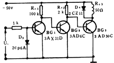
The single-ended DC amplifier needs to solve the DC level configuration problem between stages. The circuit in the following figure (a) uses the resistor Re2 to lower the emitter potential of BG2 to meet the DC level configuration requirements (that is, Ube2 = Uc1-Ue2). The following figure ( The circuit of b) uses D1 and D2 for level configuration. Let BG2 and BG3's partial listening bias voltages be Ube2 = 0.3V and Ube3 = 0.45V, respectively. D3 plays a protective role to avoid excessive back pressure on the base of BG1. If the main output voltage of the previous stage differs from the input voltage of the latter stage, the stable voltage of the silicon regulator can be used to replace the role of the silicon diode. The circuit in Figure C below uses larger Rc1 and Rc2 to increase the collector voltage to achieve the configuration of the DC level of the front and back stages. The circuit in Figure D below uses PNP (BG1 and BG3) and NPN (BG2) to reverse the polarity to configure the level. The input current achieves better inter-stage coupling. The biggest disadvantage of the above four circuits is the large zero drift. |
 |  |
 |  |
| Second, the differential DC amplifier | |
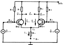
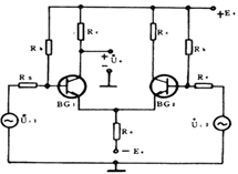
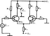
| Figure 2 (a) is a type of differential DC amplifying circuit. It consists of a pair of BG 1 and BG 2 transistors with the same characteristics, and the circuit elements are also symmetrical. The input signals are U i1 and U i2 ; the single-ended output signals are U c1 and U c2 ; the double-ended output is the difference between UC1 and UC2, that is, UO = UC1-UC2O differential circuit has the following characteristics: 1. The differential circuit with the ability to suppress zero drift has the same tube characteristics and symmetrical circuit components, so when the temperature increases, the collector current of the two tubes will get the same increase, that is, â–³ I C1 = â–³ I C20 and double-ended The output is U O = â–³ I C1 R C- â–³ I C2 R C = 0, so there is no zero drift in the output. 2. With common-mode input, a pair of input signals with equal amplitude and same phase is usually called a common-mode signal with the ability to suppress amplification. It can be seen from the following circuit diagram A. When U i1 = U i2 , under symmetrical conditions, then Double-ended output Uo = KU il -KUi2 = 0, 3. When the differential mode is input, the pair of input signals with the same amplitude and opposite phase is usually called the differential mode signal. When U i1 = -U i2 differential mode input, the output of the two-side three-knife tube collector is U c1 = -KU i1 and U c2 = -KU i2 respectively ; therefore, the differential mode magnification Kud: K ud = (U c1 -U c2 ) / (U i1 -U i2 ) = (-U i1 KU i1 K) / 2U i1 = -K = (-) (h fe R c ) / (R s + h ie ) Because the double-ended input voltage and the double-ended output voltage of the differential circuit are doubled than the single-tube common-fire amplifier circuit, the differential mode amplification Kud is the same as the single-tube common-fire circuit to improve the ability to suppress zero drift The common mode amplification factor should be as small as possible, and the differential mode amplification factor as large as possible. Therefore, the common mode rejection ratio CMRR * = Kud / Kuc is used as an important index to evaluate the performance of the differential amplifier circuit. | |
| figure 2 | |
 |  |
 |  |
| 4. The ability to stabilize the static operating point The emitter resistance Re of Figure 2 (a) has a strong negative feedback effect on the common mode signal and the temperature drift level. For example, when the temperature rises, both Ic1 and Ic2 increase at the same time, and the following negative feedback process occurs: |
 |
| As a result, the actual changes of I C1 and I C2 are relatively reduced, where Re plays a constant current role, thereby stabilizing the static operating point. Obviously, the larger the Re, the greater the constant current effect, and the stronger the ability to suppress zero drift. , The introduction of auxiliary electricity to counteract the repression of Re. So that the extreme radiation to ground potential can maintain normal values. It is worth noting that Re does not have a negative feedback effect on the differential mode signal, so it will not reduce the amplification of the differential mode signal. |
| ||||||||||||||||||||||||||||||||||||||||

Follow WeChat

Download Audiophile APP

Follow the audiophile class
related suggestion
& n ...
The servo motor is a traditional motor. It is the actuator of an automatic device. Servo motor ...
![[Photo] DC motor control circuit album-6](http://i.bosscdn.com/blog/20/06/41/6172934723.gif)
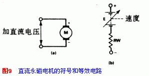
Permanent magnet commutator DC motor is a widely used one. Just apply proper voltage on it. The motor rotates. Figure 9 is ...
Four-phase stepper motors are available with several special integrated circuit drivers, SAAl027 is its ...
![[Photo] DC motor control circuit album-3](http://i.bosscdn.com/blog/20/06/41/6172910300.gif)
There are two basic forms of stepper motors: variable reluctance type and hybrid type. The basics of stepper motor ...
![[Photo] DC motor control circuit album-2](http://i.bosscdn.com/blog/20/06/41/617296993.gif)
