One. Foreword:
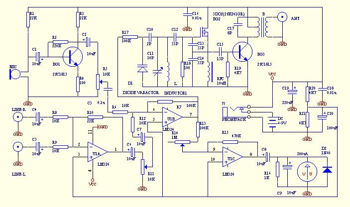
Here I will introduce a simple FM transmitter that is easy to manufacture. It not only satisfies the requirement of transmitting distance, but also can input sound signal with microphone and line at the same time to perform background dubbing. The circuit also adds a modulation monitoring meter to better grasp and use the transmitter. The circuit is shown in the following figure. After a brief introduction, do you think it has as many functions as a set of broadcasting station equipment? Yes, this small transmitter can help you easily build an amateur FM radio station! Coverage is around 500M. Move your heart, act now!

two. Circuit principle and component selection:
After the microphone picks up the signal, it enters the voltage negative feedback single-tube amplifier composed of BG1 and the peripheral circuit through C1 coupling, and amplifies the weak voltage signal to a sufficient amplitude to enter the U1B for mixing with the amplified line input signal of U1A. The mixed signal is demodulated by R17 all the way by the BG2 field effect tube and the surrounding circuit. The test ratio LC oscillator is characterized by a simple three-point oscillator with ordinary capacitance and high efficiency. High stability. The waveform is good, and the modulation bandwidth is particularly important for amateur-made FM transmitters. Finally, the post-stage amplifier cast by BG3 is amplified and transmitted outward through the transmitting antenna, and the radio can be listened to with a common FM radio. The other signal is amplified by an amplifier composed of U1C and then driven by a D2 simple wave rectifier to drive a micro-ampere meter with DC to monitor the modulation amplitude of the signal. The degree of modulation should not exceed 85% when used. The integrated circuit adopts universal four op amps such as LM324, forming a single power supply reverse input working mode, that is, the voltage of the positive phase input terminal is set at half of the power supply voltage. The monitoring head is 200u type, BG1.BG3 uses 2SC1815. BG2 uses 3DO2 field effect tube, D2 varactor diode uses 1S2267. The antenna requires the use of 1/4 wavelength, such as using a whip antenna, it is best not to be less than one meter. Otherwise, the overdue launch effect will not be achieved.
three. Afterword:
This circuit was not designed by me. It was excerpted and adapted from an unknown magazine that I picked up from the junk pile due to the shortage of electronic materials in my early years. The original circuit is attached with printing plates and assembly drawings. Digest magazines of this kind are now rare. Thanks again to the original author! Note that the use of the transmitting circuit should not interfere with normal radio broadcasting. Finally, I wish you a good time.

Follow WeChat

Download Audiophile APP

Follow the audiophile class
related suggestion
Many radio enthusiasts want to make an FM transmitter, especially in 87 ~ 10 ...


![[Photo] Self-made 5 Watt FM Transmitter](http://i.bosscdn.com/blog/20/06/41/520493168.jpg)
![[Photo] BA1404 small stereo FM transmitter](http://i.bosscdn.com/blog/20/06/41/5204442643.gif)
Author: Lin Changhao This article describes several mining ...
![[Photo] Using MEC002A to make a remote FM transmitter](http://i.bosscdn.com/blog/20/06/41/5204128230.gif)